
Home / Products / PV Combiner Box

Photovoltaic array protection · engineering category

PV Combiner Box
Engineered Around Your Array

Consolidate PV string circuits into a documented, maintainable output assembly. WILLING supports project review for plastic DC, metal DC and separately engineered AC combiner boxes.

South Africa project support Saudi Arabia / KSA documentation Spain / España technical selection Global EPC supply

Accuracy boundary: values shown on this category page are supplied-catalogue references, not a universal model declaration. Exact ratings, component brands, certificates and project acceptance must be verified against the selected assembly and current documents.

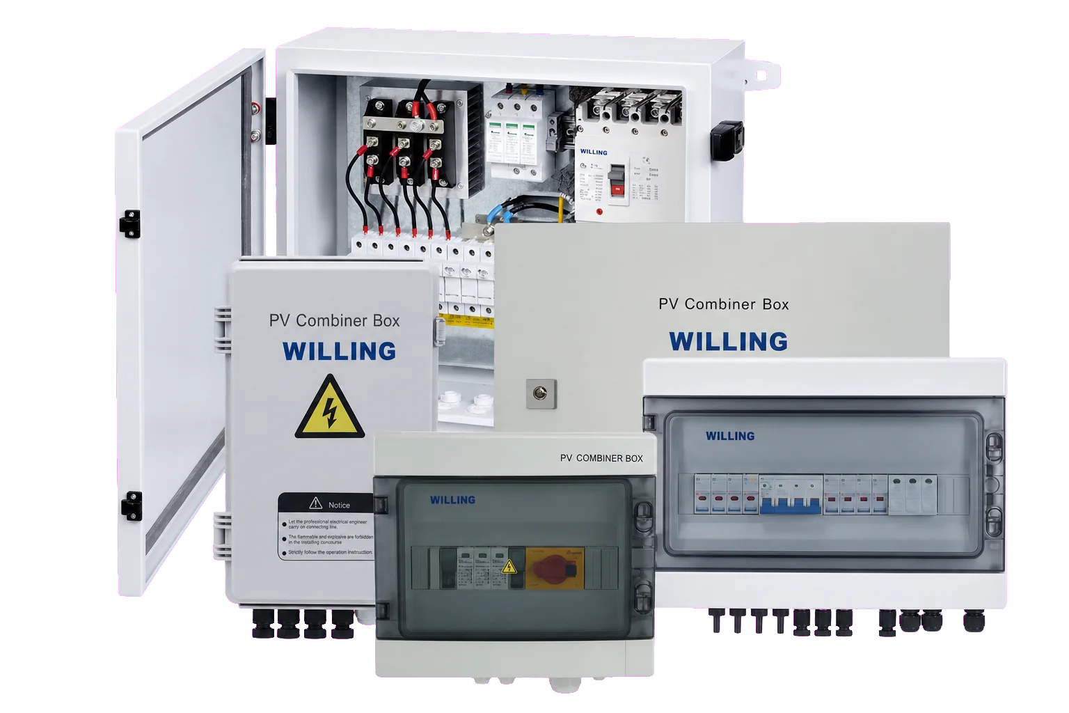
CATEGORY OVERVIEW Plastic and metal photovoltaic combiner box family overview
DC and AC families kept separateReference imagery · model selection required

AI Quick Answer: What is a PV combiner box?

A PV combiner box combines multiple photovoltaic string circuits into a coordinated output circuit before the inverter. Depending on the verified design, it may include gPV fuses, busbars, DC surge protection, a breaker or isolator, terminals, earthing and monitoring. Selection starts with cold-corrected array voltage, string current, reverse-current risk, MPPT topology and site conditions—not string count alone.

Technical review
16 July 2026
Evidence-aware content

Product-family boundary

Select the enclosure and electrical architecture separately

The enclosure material does not determine the full electrical rating. Confirm the exact input/output arrangement, protective devices, thermal design, gland plan and evidence pack for every quoted configuration.

DC FAMILY Plastic DC PV combiner box angled reference view

Plastic DC PV Combiner Box

Compact non-metallic enclosures for project-matched PV string aggregation and DC-side protection.

  • Input and output count selected by array and MPPT topology
  • String protection strategy based on reverse-current analysis
  • SPD, isolation and cable-entry arrangement require coordination

Supplied imagery is a configuration reference. Component make, ratings and availability must be confirmed in the quotation BOM.

DC FAMILY Metal DC photovoltaic combiner box interior reference view

Metal DC PV Combiner Box

Metal-enclosure assemblies for higher string counts, project-specific output circuits and serviceable internal layouts.

  • Thermal rise and corrosion protection checked for the installation site
  • Busbar, earthing and segregation designed for the selected architecture
  • Monitoring can be reviewed as an optional engineered function

Internal layout shown is illustrative. Do not infer a model-specific BOM, certification or current rating from the image.

SEPARATE AC FAMILY

AC Combiner Box

AC aggregation and protection must be engineered as an AC assembly. DC voltage, DC fuse and PV SPD data do not transfer to this family.

  • System voltage, phases, neutral and earthing selected for the AC network
  • Protective-device coordination and fault level verified independently
  • Installation and authority documents follow the AC project scope

AC parameters are intentionally not populated from DC catalogue tables. Request a project-specific AC schedule and single-line diagram.

Supplied-catalogue reference

Start the selection conversation—then verify the exact model

This matrix summarizes the current supplied catalogue family. It is not a released product datasheet and must not replace an approved quotation schedule.

Product familyInput / output referenceVoltage referenceOutput-current referenceEnclosure referenceVerification action
Plastic DC 1–6 inputs
1–3 outputs
Catalogue reference
600 / 1000V DC
Catalogue reference
32 / 63A typical; one 100A configuration appears in source material
Resolve by model
PC · IP65 · IK10
Evidence pending
Confirm model code, SLD, BOM, operating voltage, string current, output device and enclosure tests.
Metal DC 2–18 inputs
1–18 outputs
Catalogue reference
600 / 1000V DC
Catalogue reference
63 / 125 / 250A
Catalogue reference
Metal · IP54 · IK10
Evidence pending
Confirm heat-rise design, coating/corrosion class, gland plate, earthing, busbar rating and assembly verification.
AC Combiner Box Project specific Project specific AC system Project specific Project and environment specific Issue an AC-only technical schedule. Do not populate from the DC matrix.

Reference status: model-prefix and rating inconsistencies exist in the supplied source material. Current model-specific datasheets, diagrams, certificate scope and test evidence are required before publication as confirmed product values.

Functional architecture

Follow the energy path through the DC assembly

Not every project uses every function. The final design depends on array fault analysis, switching strategy, earthing, monitoring and the inverter interface.

01

PV Strings

String Voc, Isc, polarity and MPPT assignment.

02

gPV Fuses

Only where fault analysis and design rules require them.

03

Busbar

Current collection, spacing, insulation and thermal design.

04

DC SPD

Ucpv, type, coordination, backup protection and lead routing.

05

Breaker / Isolator

Verified protection or switching function; not interchangeable by assumption.

06

Inverter

Output circuit matched to DC input and MPPT architecture.

Engineering boundary

A combiner box does not create MPPT or replace system design

It organizes and protects circuits according to an engineered scheme. It does not add an MPPT channel, provide rapid shutdown unless specifically engineered to do so, or make an unsuitable inverter input compatible.

  • Maintain string compatibility within each combined group
  • Check maximum reverse current and module fuse limits
  • Keep DC and AC assemblies electrically distinct
  • Coordinate conductor, terminal and protective-device ratings
Front view of a plastic DC photovoltaic combiner box reference configuration
Reference configuration image. Visible components and markings are not model-specific availability or certification claims.

EPC selection workflow

Eight checks before requesting a quotation

Provide calculated system data and environmental conditions. A product name or requested string count alone is not enough to select a safe assembly.

01

Maximum DC voltage

Calculate maximum array Voc at the project minimum temperature and keep it within every series component rating.

02

Current & backfeed

Provide string Isc, parallel-string count, inverter backfeed limits and conductor ampacity under expected temperature.

03

String / MPPT map

Define which strings may be combined and which outputs must remain separated for inverter MPPT channels.

04

Fuse-pole strategy

Determine fuse need and polarity from reverse-current analysis, earthing and the applicable array-design rules.

05

Surge protection

Specify SPD type, Ucpv, discharge requirements, backup protection, earthing and coordination with downstream SPDs.

06

DC switching

Define whether overcurrent protection, isolation, load switching or combined functions are required and verify utilization ratings.

07

Environment

State ambient range, altitude, UV, dust, water, salt, pollution, corrosion and mounting location. Assess heat rise and derating.

08

Evidence package

List required drawings, BOM, component certificates, assembly verification, declarations, inspection records and language needs.

Do not choose only by “1000V”, “IP65” or the number of strings. Those labels do not establish cold-voltage suitability, short-circuit coordination, temperature performance, component compatibility or destination-market acceptance.

Regional project guidance

Local project questions, globally consistent engineering

Regional guidance is attached to useful engineering and procurement decisions. No local approval is implied by country targeting.

South African flag

Primary market

South Africa

For a PV combiner box in South Africa, review the electrical assembly together with the array design, inverter interface, site environment and the project’s compliance route.

  • Check cold-corrected Voc, DC fault protection and isolation against the project design.
  • Assess UV, heat, altitude, dust and coastal corrosion for the actual site.
  • Keep product evidence, installation CoC responsibilities and grid-connection requirements distinct.
PV combiner box South Africasolar combiner box supplier South AfricaPV string combiner box

Reference boundary: NRS 097 can form part of an embedded-generation grid-interface route where applicable; it is not presented here as a combiner-box product certificate. Confirm current municipal, utility and project requirements.

Saudi Arabian flag

Primary market

Saudi Arabia

A DC combiner box supplier for Saudi Arabia should support thermal, dust, UV, cable-entry and documentation review for the actual project—not rely on a generic enclosure label.

  • Provide the design ambient, solar exposure, dust and site-maintenance assumptions.
  • Verify enclosure heat rise and component derating at the project condition.
  • Confirm the current product-scope decision and import/conformity document path before shipment.
PV combiner box Saudi ArabiaDC combiner box supplier KSAsolar combiner box Riyadh

ملاحظة هندسية: يجب التحقق من متطلبات المشروع ووثائق المطابقة والظروف البيئية قبل اختيار صندوق تجميع الطاقة الشمسية.

Reference boundary: SASO, SABER or IECEE-related pathways depend on current product scope, classification and project requirements. This page makes no Saudi approval claim.

Spanish flag

Primary market

Spain

For a caja combinadora fotovoltaica en España, coordinate the product evidence with the PV installation design, protective-device selection and project documentation.

  • Verify maximum DC voltage, short-circuit current and MPPT grouping.
  • Review SPD coordination, DC switching, cable entries and protective earthing.
  • Separate CE product documentation from installation and commissioning responsibilities.
caja combinadora fotovoltaicacaja de strings fotovoltaicacuadro de protección DC fotovoltaico

Nota técnica: verifique la tensión máxima, las corrientes de cortocircuito, el SPD, el seccionamiento y la documentación del proyecto antes de la compra.

Límite de referencia: REBT e ITC-BT-40 provide installation context where applicable; they are not presented as product certification. Confirm the current project and authority route.

Installation · commissioning · maintenance

Protect performance through the full field workflow

Only qualified personnel should work on PV DC circuits. Follow the approved design, isolation procedure and model-specific instructions.

01 · BEFORE INSTALLATION

Verify the delivered assembly

Match labels and documents to the approved schedule.

  • Model, voltage and current
  • SLD and BOM revision
  • Enclosure and gland plan
  • Damage and seal inspection
02 · INSTALLATION

Control polarity and workmanship

Keep conductor routing clear and maintain protective-device coordination.

  • Verify string polarity
  • Use compatible terminals
  • Apply documented torque
  • Maintain bend radius and PE
03 · COMMISSIONING

Complete pre-energization and functional checks

Follow the project-approved sequence and component instructions.

  • Continuity and polarity before energization
  • Isolate SPD and electronic monitoring as instructed before insulation testing
  • Compare string current only after controlled energization
  • Verify SPD, switch and monitoring status
04 · MAINTENANCE

Inspect by risk and environment

Set frequency from manufacturer guidance, site exposure and operating history.

  • Heat and discoloration
  • Water, dust and corrosion
  • Loose or damaged entries
  • SPD indication and records

PV combiner box troubleshooting guide

Observed conditionSafe first checksPossible engineering causesRequired action
One string shows no currentIsolate according to procedure; inspect fuse indication, polarity, connectors and conductor continuity.Open fuse, open circuit, reversed polarity, connector fault, module/string fault or monitoring issue.Find and correct the root cause before replacing protection. Never uprate a fuse without redesign.
Hot terminal or discolorationDe-energize, record location and inspect termination, conductor and loading.Loose joint, incorrect torque, incompatible terminal, overload, corrosion or insufficient thermal design.Replace damaged parts and re-verify torque, conductor sizing, current and heat rise.
SPD status indicates replacementUse the model instruction; inspect associated backup protection and earthing path.Surge event, end-of-life indication, coordination issue or abnormal voltage.Replace only with a verified compatible module and investigate system conditions.
Water, condensation or corrosionIsolate if safety may be affected; inspect seals, glands, drainage and mounting.Incorrect entry, damaged gasket, unsuitable enclosure, temperature cycling or site exposure.Do not reseal over contamination. Correct the enclosure design and assess all affected components.

EEAT & procurement control

Ask for traceable evidence—not a row of logos

The status below is intentionally conservative. A standard listed as a design reference is not a declaration of product compliance.

Category catalogueSupplied product-family reference; inconsistent entries require model-level resolution.Reference
Model-specific datasheetVoltage, current, strings, outputs, environment and component schedule.Request current file
Single-line diagram & BOMTraceable architecture, protective devices, cable entries and component models.Pending by model
Assembly verificationDesign/routine verification evidence appropriate to the declared assembly scope.Pending review
Component certificatesCurrent scope for fuse, SPD, breaker/isolator, terminals and enclosure.Pending by BOM
IP / IK evidenceTest evidence for the complete assembly and cable-entry arrangement, not only an empty enclosure.Pending by model
Installation & inspection filesTorque, conductor, mounting, commissioning, maintenance and replacement instructions.Request current file
Regional conformity packDestination-specific declarations, importer/supplier records and authority documents.Project review
PV combiner box with monitoring components shown as a configuration reference
Monitoring configuration reference image. Visible brands, component models and ratings are not promises of the quoted BOM.

Optional engineered function

Monitoring begins with a defined data requirement

“Smart combiner box” should describe measurable functions and interfaces. Define what the project needs to detect, how data is powered and communicated, and who owns alarm response.

  • String-current measurement range, accuracy and channel count
  • DC voltage, SPD status, breaker status and enclosure sensors
  • Communications protocol, isolation, addressing and cybersecurity boundary
  • Local display, SCADA integration, alarm thresholds and maintenance access

Technical procurement FAQ

PV combiner box questions engineers and buyers ask

Concise answers are paired with visible engineering boundaries so essential safety context remains clear during product evaluation.

What does a PV combiner box do?

A PV combiner box brings multiple photovoltaic string circuits into a coordinated output circuit and can house project-selected string protection, surge protection, isolation, terminals, busbars and monitoring. The exact functions depend on the verified design.

When is a solar DC combiner box required?

There is no universal “more than three strings” rule. Need is determined by inverter input architecture, MPPT allocation, reverse-current analysis, cable routing, isolation, monitoring, maintenance and the applicable project standard.

Does every PV string need a fuse?

Not automatically. String-fuse need and pole arrangement should follow calculated reverse current, module maximum series-fuse rating, conductor protection, array earthing and the applicable design standard.

How is the DC SPD selected for a combiner box?

Select the SPD from the maximum array voltage including cold-condition correction, system earthing, required SPD type, Ucpv, discharge ratings, short-circuit coordination, backup protection and installation lead length.

What is the difference between a DC breaker and a DC isolator?

A breaker provides a verified overcurrent protection function within its ratings. An isolator provides a verified switching and isolation function. Do not treat the devices as interchangeable unless the selected device is documented for both required functions.

Should I choose a plastic or metal PV combiner box?

Choose from the complete site and assembly requirement. Compare UV, corrosion, impact, ingress, heat rise, earthing, weight, gland arrangement, service access and evidence for the complete assembly—not enclosure material alone.

What documents should an EPC request before purchasing?

Request a model-specific datasheet, single-line diagram, bill of materials, component certificates, assembly verification evidence, enclosure rating evidence, terminal and torque instructions, inspection plan, declaration documents and a traceable revision record.

Can the same specification be used in South Africa, Saudi Arabia and Spain?

Not without review. Electrical architecture, ambient conditions, installation rules, grid and authority requirements, import documentation and project specifications differ. Verify the exact destination and project evidence before selection.

Engineering quotation input

Send the array data—not only a product photo

Provide maximum cold-condition Voc, string Isc, input/output count, MPPT map, fuse strategy, SPD requirement, switching function, site conditions, destination, quantity and required documents.

WhatsApp