1 Pole
250V DCFor lower-voltage DC circuits where the selected wiring and isolation method is suitable.

CSB6-63 · Solar DC Protection
A compact thermal-magnetic DC MCB for photovoltaic and DC distribution applications. Select the pole configuration by system voltage and verify project compliance before procurement.
Engineering note: *Working voltage depends on pole count: 1P 250V, 2P 600V, 3P 800V and 4P 1000V DC. Certification marks in supplied material are document references only; current model coverage must be confirmed.
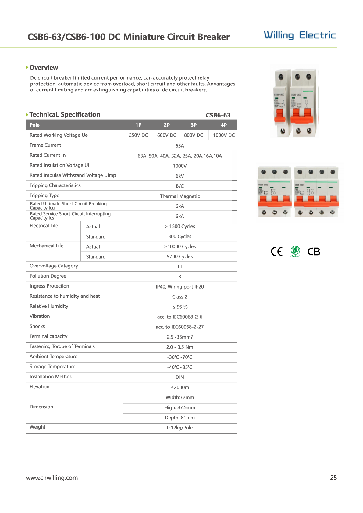
For a solar DC circuit breaker, start with maximum continuous DC voltage, prospective current and fault level—not nominal module voltage alone. CSB6-63 provides model-dependent 250–1000V DC coverage, 10–63A current options, B/C trip curves and 6kA Icu/Ics. Australia and UAE projects require market- and authority-specific document review before approval.
Pole–voltage coordination
Verified from the supplied CSB6-63 datasheet. Do not treat all pole options as interchangeable at 1000V DC.
For lower-voltage DC circuits where the selected wiring and isolation method is suitable.
Two-pole configuration for model-matched photovoltaic and DC distribution circuits.
Three-pole configuration; confirm wiring topology and polarity documentation.
Highest listed working-voltage option in the supplied CSB6-63 reference table.
Technical data
| Rated current In | 10, 16, 20, 25, 32, 40, 50, 63A |
|---|---|
| Rated insulation voltage Ui | 1000V |
| Impulse withstand Uimp | 6kV |
| Tripping type / curve | Thermal magnetic · B / C |
| Icu / Ics | 6kA / 6kA |
| Terminal capacity | 2.5–35mm² |
| Terminal torque | 2.0–3.5N·m |
| Ambient temperature | −30°C to +70°C |
| Ingress protection | IP40 body · IP20 wiring port |
| Installation | DIN rail |
| Dimensions | 72 × 87.5 × 81mm reference |
Engineering workflow
Calculate array maximum open-circuit voltage at the minimum site temperature and select the required pole configuration.
Review string current, parallel-string backfeed and equipment limits before choosing the rated current and trip curve.
Confirm the installation fault level does not exceed the selected device breaking capacity.
Check conductor size, terminal capacity, tightening torque, enclosure heat rise and cable termination practice.
Request model-specific reports, declarations, markings and authority evidence for the destination market.
Certification evidence ledger
Marks visible in supplied product material are displayed as document references—not as verified certification claims.
CE marking is visible in the supplied CSB6-63 catalogue material.
RoHS marking is visible in the supplied CSB6-63 catalogue material.
CB mark is visible in the supplied CSB6-63 catalogue material.
Evidence rule: a logo alone does not confirm the certificate number, current validity, manufacturing-site scope or inclusion of every current and pole configuration. Request the exact model-specific document set before specification.
Application boundary
Final suitability depends on system topology, available fault current, coordination and model-specific evidence.
String overcurrent protection where the calculated reverse-current condition requires a protective device.
Compact DIN-rail protection for segregated DC branches and maintenance-friendly circuit organization. Review the complete PV combiner box selection guide for enclosure-level coordination.
Feeder protection only after checking inverter limits, DC voltage, isolation strategy and fault level.
General DC branch protection within the verified ratings and environmental conditions of the selected model.
⚠Battery systems: do not assume suitability for the main battery protection device. Battery fault current can be high; verify DC breaking capacity and the exact application before selection.
Regional engineering
Regional guidance connects environmental, electrical and document requirements to the exact project decision.

Primary market
For EPCs and distributors sourcing a solar DC circuit breaker in Australia, the product rating is only the first screen. The evidence path must match the device scope, installation and local electrical equipment requirements.

Primary market
A solar DC MCB supplier in the UAE should support engineering review for high ambient temperature, dust, UV and authority-specific project documentation—not only quote a 1000V DC label.
Open the UAE solar DC project centre →
قاطع تيار مستمر للطاقة الشمسية الإمارات
Protection-device comparison
| Decision factor | DC MCB | DC MCCB | gPV Fuse | DC Isolator |
|---|---|---|---|---|
| Primary function | Branch overcurrent protection | Higher-current feeder protection | PV string overcurrent protection | Manual isolation |
| Resettable | Yes | Yes | No — replace fuse-link | Not an overcurrent device |
| Typical selection focus | Curve, current, voltage, poles, kA | Frame, trip unit, coordination, kA | gPV class, current, voltage, holder | Utilization category, poles, voltage |
| Engineering caution | Verify DC pole wiring | Check setting and discrimination | Confirm thermal derating | Do not use as overload protection |
Installation & maintenance
De-energize the DC circuit, apply the approved isolation process and confirm absence of voltage before work begins.
Use compatible conductors and ferrules where applicable. Tighten within the listed 2.0–3.5N·m reference range and follow the exact device instruction.
Check for heat discoloration, loose terminations, contamination, enclosure temperature and signs of abnormal operation during scheduled maintenance.
Technical FAQ
No. The supplied reference table lists 1P at 250V DC, 2P at 600V DC, 3P at 800V DC and 4P at 1000V DC. Select by maximum system voltage and the verified wiring configuration.
No Australian approval claim is made on this page. Request the current model-specific test reports, declarations, markings, RCM or EESS evidence and supplier information, then confirm the applicable project and regulatory path.
No DEWA approval claim is made on this page. Dubai projects should be checked against current DEWA requirements and the exact project equipment-acceptance process.
Provide maximum DC voltage, required pole count, continuous current, trip curve, prospective fault current, conductor size, quantity, destination market, enclosure conditions and required compliance documents.
Engineering document request
Send your voltage, current, pole count, destination market and documentation checklist. WILLING Electric will match the request to the available product evidence.
Share the model, voltage, pole count, quantity, destination and document requirements for a focused technical response.